Converter Accessories
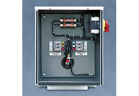
Automatic Controls
Adds built-in fuses, magnetic starter, terminal blocks, and time delay relay to allow converter to be turned on and off by the load controller in unattended applications. Standard in configurations MA-A
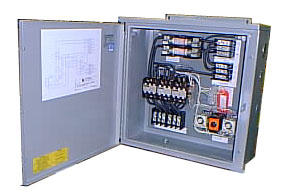
Reduced In-rush Current Starting
Special magnetic controls that reduce the converter starting current by 70% are “friendly” to weak utility services and avoid excessive power demand on the incoming service.
Outdoor Weatherproof Enclosure
Pad mounted fiberglass enclosure for outdoor installations includes pre-wired ventilating fans and provision for padlocking.
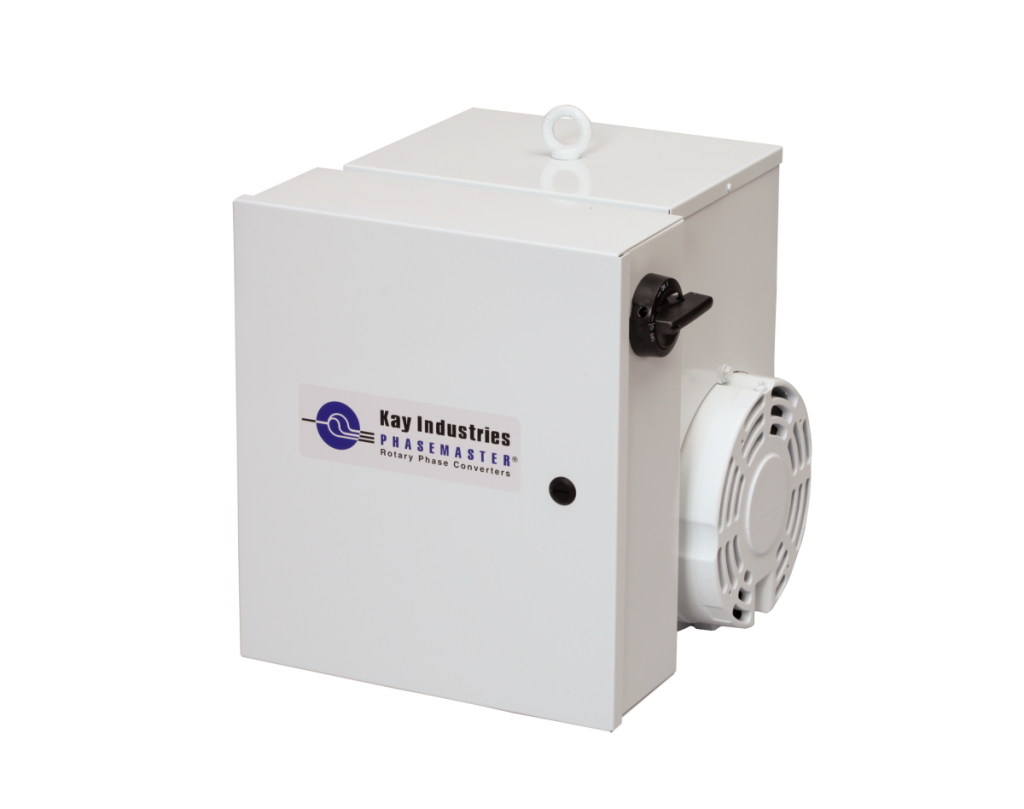
Primary Disconnect Switch Fuses
Adds built-in switch, fuses, and terminal blocks to speed installation and provide a single-point on-off converter control. Standard in configuration MA-R
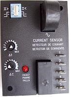
Voltage Regulation for CNC Machines (-VS)
Especially designed for CNC applications and for variable frequency drives. Enables the converter to maintain balanced output voltages over a wide load range.
The Load Range monitoring and adjustment control maintains the converter output voltage within a balanced range up to the maximum output of the converter. Its purpose is to compensate for a load which is insufficient to bring the converter output voltage into balance with the utility supplied voltage in order to prevent excessive imbalance of currents within the load.
In a rotary phase converter, the voltage of the manufactured leg varies according to the amount of connected load. Under no-load conditions this voltage will be within 5% of utility voltage. As load is applied, the manufactured phase drops rapidly into balance with the other two lines as the load increases to about 25% of converter capacity and remains there over the remainder of the range. Under most load conditions all three phases will balance to within 2-5%, which is acceptable for nearly all induction motors.
In applications involving multiple motors, the load varies as different motors come on and off line. The converter must be sized for the largest load, but there are times when only a small portion of the load is connected. Under this condition the manufactured phase voltage is too high and could cause nuisance tripping of the small motors. When the large motor comes on line, the voltage is balanced and the problem goes away.
The Load Range Controller monitors the manufactured phase current and operates a relay when this current moves above or below a preset level. When a portion of the load is added to or disconnected from the converter, the manufactured phase current changes. The Controller determines whether the new current level is outside of the allowable range. If so, the relay adjusts the converter output bringing it to an acceptable level within a short time to balance the current before the load is affected.
The controller is adjusted at the factory but may require additional fine adjustment to function properly in various loads and input voltage conditions.
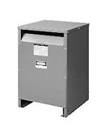
Transformers for Special Output Voltages
Step-Up: Used where supply voltage is 240V, 1-phase but 480V, 3-phase output is required. Connection diagram
Delta-Wye: To change the converter output from 3-wire delta output to 4-wire wye. Connection diagram
Buck-Boost: To reduce or increase input voltage by 10-15%. Change 240V supply to 208V or vice versa. Connection diagram
Lightning Protection- Factory installed lightning and surge protection provides first line protection against incoming line surges. Use this feature in remote areas or high elevations subject to frequent electrical storms or line disturbances.
