
E-Phase Recommended Phase Perfect® Digital Phase Converter

Congratulations! If you are reading this page, you have most likely decided to get the most voltage balanced, and quietest of all phase converters. The Perfect Phase® is the best engineered, most reliable (non-rotary) Electronic Phase Converter you can buy.
This installation page is specific to the Model PTE.
Mounting the Phase Perfect® Model PTE
- Attach mounting brackets to back of unit with the hardware supplied by the manufacturer with your PTE digital phase converter.
- It is wisest to mount the unit to a solid, non-flammable surface capable of holding a minimum of 100 lbs. using the mounting brackets provided with the PhasePerfect® PTE unit.
- Similar to a Phasemaster Rotary Converter, digital converters get hot. Make certain the air intake and exhaust openings are not obstructed. If mounted in a small room or cabinet, ensure temperature will remain below 40C (104F). Note: 18″ (450mm) clearance below and 6″ (150mm) around required for ventilation. Since heat rises the Model PTE Phase Perfect® is well vented on the top; see image below.

- Your converter comes with a warning label stating to NOT remove the outer cover. Instead you are to call Kay Industries for support. This is a note for the end-user. If you are an electrical contractor, or know what you are doing, proceed with caution.

- Start by removing the screws on each side and front of the Phasemaster® digital phase converter unit.
- Now, with the screws removed, GENTLY remove the outer cover of your digital phase converter by GENTLY lifting and pulling forward.
- Route cables through the supplied openings in the bottom of the enclosure, using appropriate conduit or strain relief devices.
terminal. Note: T3 is the manufactured leg on standard models. T2 and T3 are manufactured on voltage-doubling models.


-
 Properly ground the phase converter according to local electrical code. Connect the ground lug to the branch circuit or service ground conductor.
 - Connect the line side input leads into the terminal labeled L1 and L2.

To add an external run/stop switch, remove the orange jumper wire and connect the switch to AUX1 and COM terminals. Caution: No voltage may be introduced on these terminals. Dry contact only.

Product Literature
Looking for a digital phase converter?
Kay Industries’ E-Phase services recommends you review this brochure.
Click the link, or the brochure image for a PDF copy for PTE and all other Perfect Models.


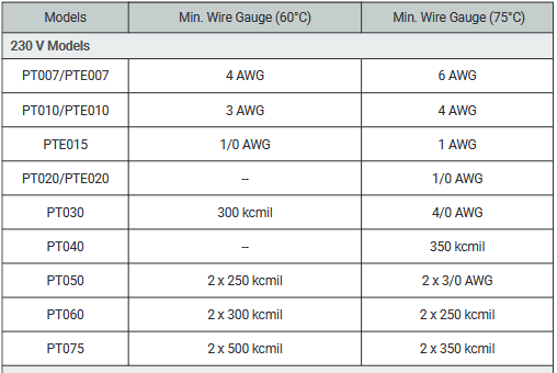
Wire Sizing Diagrams
E-Phase recommeded wiring sizing for standard Phase Perfect PTE models
Powering up the Model PTE – Phase Perfect®
- GENTLY replace the cover and secure using the previously removed screws.
- Turn on the line side breaker and verify screen turns on. Note: Once the unit is fully energized the internal contactor will pull in. Once this occurs a light sizzling noise will be emitted. Good news, this is normal.
Note: Output is in high-leg delta configuration. Leg to leg voltage will match input voltage, leg to ground will be higher on T3 than T1/T2.